Prekast Beton Duvar Paneli ve Zemin Döşemeli Ev İnşaatı: Kapsamlı Bir Süreç Kılavuzu
Özet
Ön dökümlü beton duvar panelleri ve zemin plakaları, montajlı (prefabrik) beton konut, endüstriyel üretimin avantajlarını, hızlı şantiye montajını, enerji verimliliğini ve sağlam yapısal stabiliteyi sunmaktadır. Geleneksel, tamamen yerinde dökümlü binalarla karşılaştırıldığında, ön dökümlü beton elemanlarla inşa edilen evler, şantiyedeki ıslak işleri önemli ölçüde azaltır, inşaat süresini kısaltır, inşaat atıklarını azaltır ve standartlaştırılmış, yönetmeliklere uygun elemanlar sağlar. Bu kılavuz, sahada test edilmiş eksiksiz bir inşaat iş akışını — şantiye tesviyesi ve temel hazırlığı, temel yapısı inşaatı, yerinde döküm iskelet kolon ve kirişleri ile ön döküm duvar panelleri ve zemin döşemelerinin montajı — adım adım ele alır ve bir prekast beton duvar paneli ekstrüderi ve bir prekast beton panel üretim makinesi her aşamada kullanılır. Ayrıca, güvenli, yönetmeliklere uygun, alçak katlı bir prefabrik beton evin inşa edilmesi için gerekli olan teknik kontrol noktalarını ve kalite standartlarını da ortaya koymaktadır.
1. Giriş: Ön dökümlü beton inşaatın neden yaygınlaştığı
Dünya çapında inşaat sektörünün endüstrileşmesi hız kazanırken, prefabrik (montajlı) inşaat, sektörün çevreci ve düşük karbonlu dönüşümünün temel yönlerinden biri haline gelmektedir. Ön döküm beton duvar panelleri ve zemin döşemeleri standart fabrika koşullarında üretilir, mukavemet kazanana kadar kürlenir ve ardından montaj için şantiyeye nakledilir — yerinde döküm yoluyla üretilen çerçeve elemanlarıyla birleştirildiğinde, bu hibrit yaklaşım yapısal bütünlük, stabilite ve inşaat hızı arasında bir denge sağlar. Kırsal kesimdeki kendi kendine inşa edilen evler, alçak katlı ofis binaları ve küçük yardımcı yapılar için yaygın olarak kullanılmaktadır.
Geleneksel, tamamen yerinde dökümlü inşaat yöntemi, şantiyede yoğun iş gücü gerektirir, uzun süreler alır, hava koşullarına duyarlıdır ve kalite kontrolü tutarsızdır. Bileşenlerin önceden imal edildiği ve modüllerin şantiyede birleştirildiği, yerinde döküm temel ve çerçeve ile birleştirilen ön dökümlü beton bileşen montajı, tamamen prefabrik yapıların sınırlı genel sertliğini etkili bir şekilde telafi eder. Bu kılavuz, temel hazırlığından ön döküm elemanların montajına kadar doğal inşaat sırasını adım adım takip ederek, hem inşaat kalitesini hem de yapısal güvenliği korumak amacıyla her aşamanın mantığını ve temel kontrol noktalarını açıklar.
Kapsam notu: Aşağıdaki iş akışı, şunlar için hazırlanmıştır: alçak katlı (genellikle 1–3 katlı) konut ve hafif ticari binalar. Çok katlı prekast yapılar için, iskelet ve prekast elemanlar genellikle, panellerin montajından önce iskeletin tamamının kurulması yerine, kat kat ilerleyen bir sırayla monte edilir; çok katlı projelerde çalışan okuyucular, bu sıralamayı duruma göre uyarlamalı ve yerel montajlı yapı standartlarına uymalıdır (8. Bölüm’deki yönetmelik referanslarına bakınız).
2. Genel İnşaat İş Akışı
Bu inşaat yöntemi, bir yerinde dökümlü temel, yerinde dökümlü çerçeve kolonları ve kirişleri ile ön dökümlü elemanların montajı. Yapısal yük taşıma davranışı ve inşaat yönetmeliklerine göre, çekirdek sıralaması şöyledir:
- Arazi tesviyesi, temel kazısı ve 3:7 oranında kireç-toprak katmanlı sıkıştırma
- Kolon temeli ve temel kirişi inşaatı
- Yerinde döküm beton çerçeve kolon ve çerçeve kiriş konstrüksiyonu
- Ön dökümlü beton duvar paneli ve zemin döşemesinin montajı
Her aşama bir sonrakiyle sıkı bir şekilde bağlantılıdır: Bir sonraki aşama başlamadan önce, bir önceki aşamanın denetimden geçmesi gerekir. Bu, sağlam bir temel, düzgün bir iskelet, bileşenlerin hassas bir şekilde monte edilmesini ve yapının genel güvenliğini ve dayanıklılığını sağlar.
3. Şantiye Tesviyesi, Kazı Çalışmaları ve 3:7 Oranında Kireç-Toprak Sıkıştırması
Temeli, evin yükü taşıyan temel yapısıdır. Şantiye hazırlığı ve kireçli toprak sıkıştırma işleminin kalitesi, genel istikrarı doğrudan belirler ve ileride meydana gelebilecek çökme, çatlama ve eğilme durumlarını önlemeye yardımcı olur; bu nedenle bu aşama, inşaatın ilk kritik aşamasıdır. Bu aşama üç bölümden oluşur: şantiye tesviyesi, temel çukuru kazısı ve katmanlı kireçli toprak sıkıştırma.
3.1 Şantiye Tesviyesi
İnşaat öncesinde, toplam istasyon ve nivelman cihazı kullanarak bina çizimleri ve şantiye topografyasına göre şantiye kotunu ve eksen kontrol hatlarını belirleyin; bina sınırlarını, kazı alanını ve çalışma bölgelerini tanımlayın. Çalışma yüzeyinin temiz ve sağlam olması için bitki örtüsünü, alüvyonu, inşaat molozunu ve yumuşak üst toprağı temizleyin. Şantiyeyi tasarım eğimine göre tesviye etmek için manuel son işlem özelliğine sahip bir ekskavatör kullanın; böylece drenajın düzgün olmasını sağlayın ve yağmur suyunun birikerek temel toprağını ıslatmasını önleyin. Tesviye işleminden sonra, şantiyenin genel yoğunluğunu artırmak ve kazı ile kireç-toprak çalışmaları için düzgün bir çalışma yüzeyi hazırlamak amacıyla bir ön sıkıştırma geçişi uygulayın.
3.2 Temel Çukuru Kazısı
“Katmanlı kazı, aşırı kazma yapılmaması” ilkesini gözeterek, temel tasarımı ve yerel jeolojik koşullara göre kazı derinliğini ve genişliğini belirleyin. İşin büyük bir kısmı için mekanik kazı kullanın; bozulmamış alt zemin toprağını bozmamak ve taşıma kapasitesini azaltmamak için tasarım taban kotunun üzerindeki son 20–30 cm’de manuel kazıya geçin. Kazı sırasında çukur eksen hatlarını, kotunu ve eğimini sürekli olarak kontrol edin ve gevşek toprağı ve birikmiş suyu derhal temizleyin. Kazı tamamlandıktan sonra taban toprak tabakasını inceleyin; yumuşak toprak veya boşluklar tespit edilirse bunları rapor edin ve taşıma kapasitesini tasarım gerekliliklerine getirmek için toprak değiştirme veya sıkıştırma işlemleriyle düzeltin.
3.3 Katmanlı 3:7 Kireç-Toprak Sıkıştırma
Çukur denetimden geçtikten sonra, 3:7 oranında kireç-toprak karışımı (hidratlanmış kireç ile sade toprağın hacimce 3:7 oranında karışımı) serin — bu, yüksek mukavemet, düşük sıkıştırılabilirlik ve iyi stabilite özellikleriyle değer verilen yaygın bir temel güçlendirme malzemesidir. Taş ve kalıntıları gidermek için toprağı önceden eleyin ve nem içeriğini optimum aralıkta tutun; böylece karıştırılan kireç-toprak karışımı, çizgi veya topaklanma olmaksızın homojen bir renk alır.
Kireçli toprağı katmanlar halinde serip sıkıştırın; her gevşek katmanın kalınlığı 20–30 cm ile sınırlandırılmalı ve kurbağa tipi tokmak veya silindir kullanılarak en az üç geçişte sıkıştırılmalıdır. Düzgün bir sıkıştırma kuvveti uygulayın ve her katmandan sonra sıkıştırma oranını kontrol edin; Sıkıştırma derecesi, maksimum kuru yoğunluğun ≥95%’sine ulaşmalıdır (ilgili yerel test standardına göre halka kesici yöntemi, kum ikame yöntemi veya nükleer yoğunluk ölçer kullanılarak kontrol edin) bir sonraki katman döşenmeden önce. Kireç-toprak tabakası tasarım taban kotuna ulaştığında, yüzeyi düzleştirin ve kürleyin — kürleme sırasında araç trafiğine izin vermeyin ve yük istiflemeyin — böylece kireç-toprak tabanı istikrarlı bir şekilde mukavemet kazanır ve sonraki temel yapısı için sağlam bir taşıyıcı tabaka sağlar.
4. Kolon Temeli ve Temel Kirişi İnşaatı
Kireç-toprak tabanı standartlara uygun şekilde sertleştikten sonra, temel yapısının inşasına başlanır. Kolon temelleri ve temel kirişleri, zemini ve üst çerçeve yapısını birbirine bağlar; binanın üst yüklerini taşır, bunları zemine eşit bir şekilde aktarır ve genel yapısal bütünlüğü güçlendirirken temeldeki deformasyonu sınırlar. Bu, temel ile üst yapı arasındaki kilit geçiş aşamasıdır.
4.1 Yerleşim Planı ve Zemin Hazırlığı
Binanın eksen kontrol noktalarını kullanarak, kolon temelleri ve temel kirişleri için konum, kenar ve yükseklik kontrol çizgilerini hassas bir şekilde belirleyin ve bunları mürekkep çizgileriyle açıkça işaretleyin. Kireç-toprak tabanın yüzeyini temizleyip düzleştirin, gevşek toz ve kalıntıları giderin ve betonun tabana sıkıca yapışması, oyulma veya çatlamanın önlenmesi için yüzeyi nemlendirin.
4.2 Demir Yerleştirme ve Kalıp
Tasarım çizimlerine uygun olarak temel ve temel kiriş donatılarını imal edin; çubuk çapını, aralıklarını ve ankraj uzunluğunu sıkı bir şekilde kontrol edin; çubuk yüzeylerinde pas ve yağ bulunmamalıdır. Önce temel donatısını yerleştirin; kafesin doğru konumlandırılması ve sağlam bir şekilde bağlanması için ana çubukları ve atkıları sabitleyin; ardından temel kirişi donatısını yerleştirin; çubukların kesintisiz olmasını, normlara uygun bindirme uzunluklarını ve bağlantı noktalarında sıkışıklık veya hizasızlık olmaksızın düzenli bir çubuk yerleşimini sağlayın. Bağlama işleminden sonra, koruyucu kaplama kalınlığının tutarlı olmasını sağlamak için beton kaplama ara parçalarını takın.
Demir kontrolünden sonra, kalıpları — çelik veya yüksek mukavemetli ahşap paneller — derzleri sıkı, boşluk veya deformasyon bulunmayacak şekilde monte edin; kalıplara yeterli sertlik ve stabilite kazandırmak ve beton dökümü sırasında şişkinlik veya harç sızıntısını önlemek için çelik borular ve ahşap ile destekleyin. Kalıp kurulumundan sonra, temel boyutlarını, kotunu ve konumunu projeye göre yeniden doğrulayın.
4.3 Beton Dökümü ve Olgunlaştırma
Tasarım mukavemet derecesine sahip hazır beton veya şantiyede harmanlanmış beton dökülmelidir. Hava boşluklarını gidermek ve yoğunluğu sağlamak için daldırmalı titreşimli çubuk kullanılarak katmanlar halinde döküm ve titreşim işlemi yapılmalı; bal peteği yapısı, çukurlaşma veya boşluk oluşumu önlenmelidir. Mümkün olduğunda kolon temelleri ve temel kirişleri tek bir işlemde kesintisiz olarak dökülmeli ve yapısal bütünlüğü korumak için inşaat derzleri en aza indirilmelidir.
Dökümden sonra yüzeyi derhal mala ile düzeltin ve tesviye edin; beton ilk sertleşmeye ulaştığında, en az 7 gün süreyle (ortam sıcaklığına ve geçerli kürleme standardına göre ayarlayarak) su ile kürlemeye başlayın ve bu süre boyunca yüzeyi nemli ve bozulmamış halde tutun; böylece temel betonunun mukavemeti, üstündeki iskelet yapının temeli olarak istikrarlı bir şekilde gelişir.
5. Yerinde Döküm Beton Çerçeve Kolonları ve Kirişleri
Temel yapısı, tasarım (28 günlük) mukavemetinin en az 70%’sine ulaştığında — aynı koşullarda kürlenmiş test küpleri/silindirleri kullanılarak doğrulanır; kesin süre beton sınıfına ve ortam sıcaklığına bağlıdır — üst katta yerinde döküm çerçeve kolon ve kirişlerinin inşasına başlanır. Çerçeve, üst yapının yük taşıyan iskeletidir: duvar panellerinden ve zemin döşemelerinden aktarılan yükleri taşır, ön döküm elemanları sabitler ve genel sertliği ile sismik performansı güçlendirir. Yerinde döküm çerçeve, ön döküm eleman birleşim yerlerindeki süreklilik kaybını etkili bir şekilde telafi ederek genel yapısal güvenliği artırır.
5.1 Dikey Yerleşim ve Temel Hazırlığı
Temel üst yüzeyinde, çerçeve kolonları ve kirişleri için eksen ve konum ölçülerini hassas bir şekilde belirleyin ve kontrol çizgilerini işaretleyin. Temel üstündeki beton temas yüzeyini pürüzlendirin, çimento sütü ve gevşek betonu temizleyin; ardından yeni ve eski beton arasındaki bağlanmayı güçlendirmek ve tabakalar arası çatlamayı önlemek için yüzeyi temizleyip nemlendirin.
5.2 Çerçeve Kolon ve Kiriş Donatıları
Çizimlere uygun olarak, dikey kolon donatısını üst üste bindirip bağlayın; bu sırada diklik ve aralıkları kontrol edin; şifreli ve şifresiz bölgelerdeki atkı aralıkları ile üst üste bindirme ve ankraj uzunlukları, tasarımın sismik gerekliliklerine kesinlikle uymalıdır. Kolon donatısı denetimden geçtikten sonra, kiriş destek iskelesini ve kiriş tabanı kalıbını kurun; ardından kiriş donatısını bağlayın. Bu sırada, kiriş-kolon birleşim yerlerindeki donatının düzgün bir şekilde düzenlenip sağlam bir şekilde bağlandığından emin olun ve tam bir yük taşıyıcı kafes oluşturun.
5.3 Kalıp Kurulumu ve Destekleme
Donatı denetimden geçtikten sonra, kolonlar ve kirişler için yan kalıpları kurun. Kalıplar düz olmalı, sıkı bir şekilde birleştirilmeli ve harç sızıntısına karşı sızdırmaz hale getirilmelidir. Dikeyliği kontrol etmek için kolon kalıplarını kelepçeler ve çelik boru desteklerle sabitleyin; kiriş kalıplarını ise dikmeler, yatay elemanlar ve krikolardan oluşan bir sistemle destekleyin. Destek aralıkları sıkı bir şekilde kontrol edilmelidir; böylece sistem, deformasyon veya oturma olmadan betonun kendi ağırlığını ve inşaat yüklerini güvenli bir şekilde taşıyabilir. Kurulumdan sonra kalıp boyutlarını, kotunu, diklik durumunu ve stabilitesini eksiksiz bir şekilde kontrol edin.
5.4 Beton Dökümü, Titreşim ve Olgunlaştırma
Çerçeve kolon ve kiriş betonunu katmanlar halinde dökün: önce kolonları döküp titreştirin; ardından kolon betonu kiriş alt yüzey seviyesine ulaştığında, kiriş-kolon birleşim yerlerinde sıkı bir yapışma sağlanması için kirişleri dökmeden önce kısa bir süre bekleyin. Titreştirme sırasında, demirlerin yerinden kaymasını veya kalıbın deforme olmasını önlemek için donatı ve kalıpla temastan kaçının. Dökümden sonra derhal mala ile düzeltin ve bileşen kotlarını işaretleyin.
Beton nihai sertleşmeye ulaşır ulaşmaz su ile kürlemeye başlanmalıdır; sıcak havalarda nemi korumak için jeotekstil ile örtülmeli ve soğuk havalarda yalıtım koruması uygulanmalıdır; kürleme süresi en az 7 gün olmalıdır. Kalıp ve destekler, ancak iskelet betonunun ön döküm eleman yüklerini taşıyabilmesi için gerekli tasarım mukavemetine ulaştıktan sonra kaldırılabilir; bundan sonra ön döküm elemanların montajına başlanır.
6. Prefabrik Beton Duvar Paneli ve Zemin Döşemesi Montajı
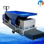
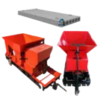
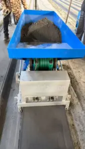
Yerinde döküm çerçeve tamamlanıp denetlendikten sonra, asıl işlem başlar: ön döküm beton duvar panellerinin ve zemin döşemelerinin montajı. Bu iş akışında kullanılan duvar panelleri ve zemin döşemeleri, özel endüstriyel ekipmanlarda seri olarak üretilir — bir prekast beton duvar paneli ekstrüderi ve bir prekast beton panel üretim makinesi — bu teknolojiler, geleneksel, emek yoğun manuel kalıplama ve şantajda döküm yöntemlerinin yerini almaktadır. Bu, malzeme israfını ve işçilik maliyetlerini kontrol altına alırken, parça üretimindeki doğruluğu ve hızı önemli ölçüde artırarak, daha hızlı ve daha düşük maliyetli bir inşaatın temelini oluşturmaktadır.
Yapısal mantık notu: Bu iş akışında, yerinde dökümlü iskelet kolonları ve kirişleri, yapının ana yük taşıyıcı iskeletini oluşturur — bunlar ilk olarak inşa edilir ve binanın yerçekimi yüklerini ve yanal yüklerini taşır. Prekast duvar panelleri taşıyıcı olmayan dolgu/kaplama elemanları tamamlanmış çerçeveye sonradan monte edilirken, ön döküm zemin plakaları ise çerçeve kirişleri üzerinde doğrudan yük taşıyan yapısal elemanlardır. Bu rol dağılımı, tam da prekast beton duvar paneli ekstrüderi Bu iş için en uygun yöntem: Sürekli ekstrüzyonla şekillendirme, büyük çaplı yapısal donatıya veya ağır gömülü bağlantı elemanlarına ihtiyaç duymayan içi boş, hafif duvar panelleri için en uygun yöntemdir; bu da, halihazırda yük taşıyıcı bir çerçeve içinde yer alan dolgu panelleri için tam olarak geçerlidir. Bu panellerin çerçeveye olan bağlantılarının, yalnızca kendi ağırlığına, düzlem dışı rüzgâr/sismik yüklere ve inşaat sırasında maruz kalacağı zorlamalara dayanması yeterlidir; yapısal yük taşıyan ön döküm kesme duvarları için gerekli olan sismik manşon/harçlı bindirme bağlantılarına gerek yoktur (bu ayrı kullanım durumunu kapsayan standartlar için bkz. Bölüm 8; bu, yalnızca bir projede yerinde döküm çerçevenin yerine yük taşıyan ön döküm duvarlar kullanılması durumunda geçerlidir).
Tüm ön döküm elemanlar, tek bir entegre işlemle ekipman üzerinde şekillendirilir, buharla kürlenir ve mukavemet testlerinden geçirilir; ardından şantiyeye nakledilerek kaldırma ve montaj işlemlerine tabi tutulur. Bu süreç, elemanlara hassas boyutlar, istikrarlı mukavemet ve yüksek tutarlılık kazandırır. Montaj, “zemin döşemelerinden önce duvar panelleri, dış duvarlardan önce iç duvarlar” sırasına sıkı sıkıya uyulur; bu sayede elemanların makul yük yolları ve sağlam bağlantılarla düzenli bir şekilde monte edilmesi sağlanır.
6.1 Kurulum Öncesi Hazırlıklar
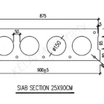
Bileşenler şantiyeye ulaşmadan önce, aşağıdakiler tarafından üretilen duvar panellerinin ve zemin plakalarının kalitesini kontrol edin: prekast beton duvar paneli ekstrüderi ve prekast beton panel üretim makinesi, teknik özellikleri, boyutları, mukavemeti ve yüzey kalitesini kontrol ederek. Her iki makine de mekanize, montaj hattı usulü üretimle çalışır: Duvar paneli ekstrüderi, beton dağıtımı, ekstrüzyon şekillendirme ve titreşim/sıkıştırma işlemlerini tek bir entegre geçişte tamamlayarak, homojen yoğunlukta ve boyut sapması asgari düzeyde olan paneller üretir; ön döküm beton panel üretim makinesi ise proje gereksinimlerine uyacak şekilde özel zemin döşeme kalınlığı ve donatı düzeni için yapılandırılabilir ve yüksek seri üretim verimliliği sunar. Geleneksel ön döküm yöntemleriyle karşılaştırıldığında, bu yöntem malzeme israfını ve işçilik maliyetini önemli ölçüde azaltır.
Malzemeleri teslim aldığınızda, panelleri ve döşeme levhalarını yüzey çatlakları, kenar ve köşelerde kırıklar veya deformasyon açısından inceleyin ve gömülü parçaların ve bağlantı deliklerinin doğru konumda olduğunu kontrol edin. Ezilme veya hasarı önlemek için bileşenleri türlerine göre, düz ve sıkıştırılmış bir depolama alanında ahşap desteklerle istifleyin — duvar panelleri dikey, döşeme levhaları yatay olarak depolanmalıdır.
Aynı zamanda, şantiyeyi temizleyin, kotları yeniden kontrol edin ve eksen çizgilerini yeniden işaretleyin. Duvar panelleri ve zemin döşemeleri için ilgili çerçeve kolon/kiriş konumlarında montaj ve yükseklik kontrol çizgilerini işaretleyin ve doğru bir montaj referans noktası sağlamak için yükseklik ayar parçaları yerleştirin. Vinç, kaldırma halatları ve hizalama aletlerini önceden kontrol edip kalibre edin ve güvenlik önlemlerini alın.
6.2 Ön Üretimli Duvar Panellerinin Montajı
Duvar panelleri, çok noktalı bir vinç sistemi kullanılarak kaldırılır. Yükün eşit dağılımını sağlamak ve kaldırma sırasında deformasyon veya çatlamayı önlemek için kaldırma noktaları, panelin ağırlık merkezine göre belirlenir. Panel, montaj konumunun üzerine kaldırıldıktan sonra, işçiler kontrol çizgilerine göre konumunu, diklik ve düzlüğünü ayarlayarak paneli hassas bir şekilde hizaya getirirken, panel yavaşça indirilir.
İlk yerleştirme işleminden sonra, paneli sabit tutmak ve devrilmesini önlemek için eşit aralıklarla yerleştirilmiş geçici desteklerle sabitleyin. Bitişik panellerin tutarlı ve eşit boşluklarla hizalanması için dikeyliği ve derz genişliğini derhal düzeltin. Düzeltme işlemi tamamlandıktan sonra, paneli gömülü bağlantı elemanları aracılığıyla yerinde döküm çerçeveye bağlayın — panelin nihai konumunu sabitlemek için kaynak veya cıvatalı sabitleme standarttır; çünkü panel, yapısal bir kesme duvarı değil, halihazırda tamamlanmış bir yük taşıyıcı çerçeve tarafından sabitlenmiş, yük taşımayan bir dolgu elemanıdır — böylece panelin nihai konumu sabitlenir.
Tüm duvar panelleri monte edilip sabitlendikten sonra, paneller arasındaki ve paneller ile çerçeve arasındaki derzleri temizleyin; ardından duvar yapısının bütünlüğünü, hava sızdırmazlığını ve su geçirmezliğini korumak için bu derzleri, tamamen sıkıştırılmış özel derz dolgusu veya ince taneli betonla doldurun.
6.3 Ön Döküm Zemin Döşemesinin Montajı
Duvar panelleri monte edilip sabitlendikten ve bağlantı derzleri yeterli mukavemete ulaştıktan sonra, zemin döşemesinin döşenmesine başlanır. Döşeme plakaları, dengeli bir çok noktalı kaldırma çerçevesi kullanılarak kaldırılır; bileşenlere zarar verebilecek veya duvar panellerini yerinden oynatabilecek darbe veya sallantıyı önlemek için yumuşak bir şekilde yukarı ve aşağı hareket ettirilir. Döşeme plakaları, yerleşim çizimlerine tam olarak uygun şekilde, çerçeve kirişlerinin üstüne veya yük taşıyan duvar panellerine, yönetmeliklere uygun sabit bir dayanma uzunluğu ile yerleştirilir.
Döşeme yerleştirildikten sonra, zemin yüzeyinin düz ve derz genişliklerinin eşit olması için döşeme aralıklarını, yüksekliğini ve düzlüğünü ayarlayın. Döşeme-döşeme ve döşeme-çerçeve bağlantı noktalarında, gömülü donatıyı sabitleyin ve kaynaklayarak döşemenin çıkıntılı çubuklarını çerçeve kirişi ve duvar paneli donatısına bağlayın; böylece zeminin genel yapı ile bütünlüğünü güçlendirin. Derzleri ince taneli betonla katmanlar halinde doldurun, iyice titreştirip sıkıştırın, ardından derz çatlamasını önlemek için derhal kürleyin.
6.4 Ortak İşleme ve Kalite Kabulü
Tüm duvar panelleri ve zemin döşemeleri monte edildikten sonra, bileşenlerin konumunu, yüksekliğini, diklik ve düzlüğünü kapsamlı bir şekilde inceleyin; ayrıca her bir bağlantı ek yerinin kaynak kalitesini, ankraj uzunluğunu ve derz dolgu yoğunluğunu kontrol ederek bağlantıların sağlam ve güvenilir olduğunu teyit edin. Montajdaki sapmaları derhal düzeltin ve kapsamlı bir yapısal öz denetim ile yeniden denetim gerçekleştirin. Ancak kabul testinden geçildikten sonra çatı kaplama, iç mekân kaplama ve diğer takip işlerine devam edilebilir.
7. Temel Kalite Kontrol Noktaları
- Temel aşaması: Kireç-toprak karışım oranını (3:7), tabaka kalınlığını ve sıkıştırma geçiş sayısını sıkı bir şekilde kontrol edin; yumuşak temel veya yetersiz sıkıştırma riskini ortadan kaldırmak ve oturmayı kaynağında önlemek için, belgelenmiş bir yöntem (halka kesici/kum ikamesi/nükleer yoğunluk) kullanarak sıkıştırma oranını tüm alan boyunca test edin.
- Temel ve iskelet aşaması: inşaat demirlerinin çapı, aralıkları ve ankraj uzunluklarını titizlikle kontrol edin; kalıp desteklerini sağlam bir şekilde sabitleyin; bal peteği yapısı, çukurlaşma veya boşlukların oluşmasını önlemek için beton dökümü sırasında iyice titreştirin; tasarım mukavemetine ulaşılmasını sağlamak için kürleme prosedürlerine harfiyen uyun.
- Prekast elemanların montaj aşaması: Elemanlar teslim alındığında titizlikle incelenmelidir; hasarı önlemek için standart kaldırma prosedürlerine uyulmalıdır; elemanlar hassas bir şekilde hizalanmalı, diklik ve düzlük sapmaları sıkı bir şekilde kontrol edilmeli ve genel yapısal sertlik ile stabiliteyi korumak amacıyla derz bağlantıları ve derz dolgularının tamamen sıkıştırılmış ve sağlam olduğundan emin olunmalıdır.
- Aşama devir kontrolü: “Bir önceki aşama denetimden geçmeden bir sonraki aşamaya geçilmez” ilkesini titizlikle uygulayın; inşaat süreci boyunca kalite kontrolünü sağlamak amacıyla her aşamada gizli iş denetim kayıtlarını belgelendirin.
8. Referans Alınacak İlgili Standartlar ve Yönetmelikler
Teknik açıdan geçerli bir inşaat kaydı elde etmek için, yukarıdaki her aşama, ilgili ulusal veya bölgesel yönetmeliklerle karşılaştırılarak kontrol edilmelidir; örneğin (Çin bağlamındaki referanslar — uygun olduğu durumlarda yerel eşdeğerleriyle değiştirin):
- Beton Yapıların İnşaat Kalitesinin Kabulüne İlişkin Standart (GB 50204)
- Bina Temel Tasarımı Yönetmeliği (GB 50007)
- Binaların Sismik Tasarımı Yönetmeliği (GB 50011)
- Ön dökümlü Beton Yapılar için Teknik Şartname (JGJ 1) ve Beton Yapılı Montajlı Binalar için Teknik Standart (GB/T 51231) — esas olarak, yerinde dökümlü iskelet yerine yük taşıyıcı ön dökümlü duvar panelleri kullanıldığında geçerlidir; Bölüm 6’da açıklanan yük taşımayan dolgu panelleri için gerekli değildir
- Bina Temel İşlemleri / Zemin İşlemleri Şartnamesi (JGJ 79)
Çin dışındaki projelerde, beton tasarımı, olgunlaştırma ve ön döküm bağlantı gereklilikleri için yerel olarak kabul edilen eşdeğer standartlar (örneğin, ABD’de ACI 318 / PCI tasarım ve inşaat kılavuzları veya AB’de Eurocode 2) uygulanmalıdır.
9. Prekast Beton Duvar Paneli Ekstrüderi ve Panel Üretim Makinesi Kullanmanın Avantajları
- Daha hızlı üretim: Sürekli ve mekanize şekillendirme işlemi, manuel kalıplama, panel kesme ve döşeme üretim sürelerini önemli ölçüde kısaltır.
- Daha yüksek boyutsal doğruluk: Makine kontrollü dağıtım, şekillendirme ve titreşim işlemleri, manuel yerinde döküm yöntemine kıyasla boyutsal sapmaları azaltır.
- Malzeme israfını ve işçilik maliyetini azaltır: Hassas harmanlama ve otomatik kalıplama, beton fazlalığını ve manuel işçilik saatlerini azaltır.
- Tutarlı kalite: Buharla sertleştirme ve hat içi mukavemet testi, her panel ve levhaya birbiriyle karşılaştırılabilir düzeyde mukavemet ve yoğunluk sağlar.
- Daha hızlı ve daha temiz şantiye montajı: Fabrikada tamamlanmış bileşenler, şantiyede ıslak işlerin miktarını azaltarak genel inşaat süresini kısaltır ve inşaat atıklarını azaltır.
10. Sıkça Sorulan Sorular
Prekast beton duvar paneli ekstrüderi ne için kullanılır?
A prekast beton duvar paneli ekstrüderi duvar paneli üretimini mekanize eder — betonun dağıtılması, şekillendirilmek üzere ekstrüzyonla şekillendirilmesi ve titreştirilerek sıkıştırılması işlemlerini tek bir kesintisiz aşamada gerçekleştirir. Bu sistem, halihazırda yük taşıyıcı olan yerinde döküm çerçeve içinde yük taşımayan dolgu veya kaplama duvarı görevi gören içi boş, hafif duvar panellerinin üretimi için idealdir; bu da tam olarak duvar panellerinin bu inşaat sırasındaki rolüdür (önce çerçeve inşa edilir, ardından paneller monte edilir).
Prekast beton panel üretim makinesi ne için kullanılır?
A prekast beton panel üretim makinesi (genellikle zemin döşemeleri için kullanılır) bileşenleri belirlenen kalınlıkta ve donatı düzeninde şekillendirerek, alçak katlı konutlar ve hafif ticari binalar için ön döküm zemin döşemelerinin yüksek hacimli ve tutarlı bir şekilde üretilmesini sağlar.
Prekast beton bir evin tipik inşaat aşamaları nelerdir?
Şantiye tesviyesi ve kireç-toprak sıkıştırması, ardından kolon temeli ve temel kirişi yapımı, daha sonra yerinde dökümlü iskelet kolonları ve kirişleri ve son olarak da ön dökümlü duvar panelleri ile zemin döşemelerinin montajı — her aşama, bir sonraki aşamaya geçilmeden önce denetlenir.
Bu yöntem çok katlı binalar için uygun mu?
Açıklandığı üzere, bu iş akışı alçak binalar için tasarlanmıştır. Çok katlı prekast yapılar, genellikle tüm iskeleti önceden tamamlamak yerine iskeleti ve prekast bileşenleri kat kat inşa ederler ve Bölüm 8’de atıfta bulunulan monte edilmiş yapı standartlarına uymalıdırlar.
11. Sonuç
Burada açıklanan aşamalı inşaat yöntemi — arazi ve temel hazırlığı → temel yapımı → yerinde dökümlü iskelet yapımı → ön dökümlü elemanların montajı — prekast beton duvar panelleri ve zemin plakalarıyla inşaat yapmanın pratik mantığıyla uyumludur. Bir prekast beton duvar paneli ekstrüderi ve bir prekast beton panel üretim makinesi, ve yerinde döküm yapı ile prefabrik elemanların ikili avantajlarını bir araya getiren bu yaklaşım, temelin ve yük taşıyan iskeletin stabilitesini ve sismik performansını korurken, mekanize prefabrik üretim ise eleman üretim kapasitesini önemli ölçüde artırır, malzeme ve işçilikten tasarruf sağlar ve şantiyede montajın getirdiği verimlilik, enerji tasarrufu ve çevresel faydaları sunar.
Her inşaat aşaması net sorumluluklar içerir ve bir sonraki aşamayla sıkı bir şekilde bağlantılıdır; şantiye hazırlığı, kireç-toprak sıkıştırması, yerinde döküm kolon ve kirişler, mekanize eleman üretimi ile kaldırma ve montaj işlemlerini özenle yöneterek, inşaatçılar ön dökümlü beton konutların kalitesini artırabilir, inşaat risklerini azaltabilir, inşaat süresini kısaltabilir ve maliyetleri kontrol altına alabilirler.
Bu inşaat süreci, alçak katlı konut inşaatı ihtiyaçlarına son derece uygundur; net ve uygulanabilir bir iş akışı sunar ve sektörün çevreci, endüstriyelleştirilmiş yapıya doğru ilerleyişiyle uyumludur; bu sayede, benzer ön dökümlü beton konut projeleri için pratik ve standartlara dayalı bir teknik referans sağlar.
Çin Prekast Beton Çit Duvar Yapma Makinesi Üreticisi | Kelai Machinery