Строительство дома из сборных железобетонных стеновых панелей и перекрытий: полное руководство по процессу
Аннотация
Сборные железобетонные стеновые панели и перекрытия являются основными компонентами монолитное (сборное) бетонное жилье, обладающие такими преимуществами, как промышленное производство, быстрая сборка на строительной площадке, энергоэффективность и высокая конструктивная устойчивость. По сравнению с традиционными зданиями, полностью возводимыми методом монолитного бетонирования, дома, построенные с использованием сборных железобетонных элементов, позволяют значительно сократить объем мокрых работ на строительной площадке, ускорить сроки строительства, уменьшить объем строительных отходов и обеспечить использование стандартизированных элементов, соответствующих нормам и правилам. В данном руководстве подробно описан полный, проверенный на практике технологический процесс строительства — выравнивание участка и подготовка фундамента, возведение фундаментной конструкции, монолитное бетонирование каркасных колонн и балок, а также монтаж сборных стеновых панелей и перекрытий — и объясняется, как экструдер для сборных бетонных стеновых панелей и машина для производства сборных железобетонных панелей используются на каждом этапе. В ней также изложены технические контрольные точки и стандарты качества, необходимые для возведения безопасного, соответствующего нормам малоэтажного дома из сборного железобетона.
1. Введение: Почему растёт популярность строительства из сборного железобетона
По мере ускорения индустриализации строительства во всем мире сборное (модульное) строительство становится одним из основных направлений экологичной и низкоуглеродной трансформации отрасли. Сборные железобетонные стеновые панели и перекрытия изготавливаются в стандартизированных заводских условиях, доводятся до необходимой прочности, а затем доставляются на строительную площадку для монтажа — в сочетании с элементами каркаса, отливаемыми на месте, такой гибридный подход обеспечивает оптимальный баланс между прочностью конструкции, устойчивостью и скоростью строительства. Он широко применяется при возведении частных домов в сельской местности, малоэтажных офисных зданий и небольших вспомогательных сооружений.
Традиционное строительство с использованием монолитного бетона сопряжено с большими трудозатратами на строительной площадке, длительными сроками выполнения работ, зависимостью от погодных условий и нестабильным контролем качества. Монтаж сборных железобетонных элементов — когда элементы изготавливаются заранее, а модули собираются на строительной площадке в сочетании с монолитным фундаментом и каркасом — эффективно компенсирует ограниченную общую жесткость чисто сборных конструкций. Настоящее руководство шаг за шагом следует естественной последовательности строительных работ — от подготовки фундамента до монтажа сборных элементов, разъясняя логику и ключевые контрольные моменты каждого этапа для обеспечения как качества строительства, так и безопасности конструкции.
Примечание: приведенный ниже рабочий процесс предназначен для малоэтажные (как правило, 1–3-этажные) жилые и небольшие коммерческие здания. В случае многоэтажных зданий из сборных конструкций каркас и сборные элементы обычно монтируются этаж за этажом по принципу «последовательного наращивания», а не с полной сборкой всего каркаса перед установкой панелей; читателям, работающим над многоэтажными проектами, следует соответствующим образом адаптировать эту последовательность и руководствоваться местными нормами по сборным конструкциям (см. ссылки на нормативы в разделе 8).
2. Общий рабочий процесс строительства
Данный метод строительства сочетает в себе фундамент, залитый на месте; колонны и балки каркаса, залитые на месте; а также монтаж сборных элементов. С учетом несущей способности конструкции и строительных норм последовательность работ по устройству ядра выглядит следующим образом:
- Выравнивание участка, выемка грунта под фундамент и уплотнение слоев из смеси извести и грунта в соотношении 3:7
- Строительство столбчатых фундаментов и фундаментных балок
- Конструкция из монолитных бетонных каркасных колонн и балок
- Монтаж сборных железобетонных стеновых панелей и перекрытий
Каждый этап тесно связан со следующим: прежде чем приступить к следующему этапу, предыдущий должен пройти проверку. Это обеспечивает прочную основу, правильную конструкцию каркаса, точную установку компонентов, а также общую безопасность и долговечность сооружения.
3. Выравнивание участка, земляные работы и уплотнение смеси из извести и грунта в соотношении 3:7
Фундамент является основной несущей основой дома. Качество подготовки строительной площадки и уплотнения известково-грунтовой смеси напрямую определяет общую устойчивость здания и помогает предотвратить появление осадок, трещин и наклонов в будущем, что делает этот этап первым и наиболее важным на строительстве. Он состоит из трёх частей: выравнивание строительной площадки, выемка котлована под фундамент и послойное уплотнение известково-грунтовой смеси.
3.1 Выравнивание участка
Перед началом строительства с помощью тахеометра и нивелира определите высоту участка и контрольные линии осей на основе строительных чертежей и рельефа местности, обозначив границы здания, зону земляных работ и рабочие зоны. Удалите растительность, ил, строительный мусор и рыхлый верхний слой почвы, чтобы рабочая поверхность была чистой и уплотненной. Используйте экскаватор с ручной доработкой для планировки участка в соответствии с проектным уклоном, обеспечивая плавный отвод воды и предотвращая скопление дождевой воды и размокание грунта фундамента. После планировки проведите предварительное уплотнение, чтобы повысить общую плотность грунта на участке и подготовить ровную рабочую поверхность для земляных работ и работ с известковым грунтом.
3.2 Выемка котлована
Определить глубину и ширину выемки исходя из проекта фундамента и местных геологических условий, руководствуясь принципом “послойной выемки без избыточного выемки”. Основной объем работ следует выполнять с помощью механизированной выемки грунта, переходя к ручной выемке на последних 20–30 см над расчетной отметкой основания, чтобы избежать нарушения целостности ненарушенного грунта основания и снижения его несущей способности. В ходе земляных работ постоянно проверяйте линии осей котлована, высоту и уклон, а также своевременно удаляйте рыхлый грунт и скопившуюся воду. По завершении земляных работ осмотрите нижний слой грунта; в случае обнаружения мягкого грунта или пустот сообщите об этом и примите меры по замене грунта или уплотнению, чтобы довести несущую способность до проектных требований.
3.3 Уплотнение слоя из известкового грунта в соотношении 3:7
После того как котлован пройдет проверку, уложите смесь из извести и грунта в соотношении 3:7 (соотношение по объему гидратированной извести к обычному грунту 3:7) — распространенный материал для укрепления фундамента, ценимый за высокую прочность, низкую сжимаемость и хорошую стабильность. Заранее просейте грунт, чтобы удалить камни и мусор, и поддерживайте влажность в пределах оптимального диапазона, чтобы смесь извести и грунта имела однородный цвет без полос и комков.
Распределяйте и уплотняйте известково-почвенную смесь слоями, при этом толщина каждого сыпучего слоя должна составлять 20–30 см, а уплотнение следует производить с помощью трамбовки «лягушка» или катка не менее чем в три прохода. Прилагайте равномерное уплотняющее усилие и проверяйте степень уплотнения после каждого слоя; степень уплотнения должна составлять не менее 95% от максимальной сухой плотности (проверить с помощью метода кольцевого резака, метода замещения песка или ядерного плотномера в соответствии с применимым местным стандартом испытаний) перед укладкой следующего слоя. Как только слой из известкового грунта достигнет расчетной высоты основания, выровняйте и дайте поверхности отвердеть — во время отвердевания запрещается движение транспортных средств и размещение грузов — чтобы известково-грунтовое основание плавно набирало прочность и обеспечивало прочный несущий слой для последующей конструкции фундамента.
4. Строительство столбчатого фундамента и фундаментной балки
После того как известково-грунтовая основа затвердеет до требуемых характеристик, приступают к возведению фундаментной конструкции. Фундаментные плиты и балки соединяют грунт и верхнюю каркасную конструкцию — они принимают на себя нагрузки верхних этажей здания, равномерно передают их в грунт, сдерживают деформацию фундамента и укрепляют общую конструктивную целостность. Это ключевой переходный этап между фундаментом и надземной частью здания.
4.1 Разметка и подготовка основания
Используя контрольные точки осей здания, точно разбейте местоположение, границы и высотные контрольные линии для фундаментов колонн и фундаментных балок, четко обозначив их чернильными линиями. Очистите и выровняйте поверхность известково-грунтового основания, удалив рыхлую пыль и мусор, а затем увлажните поверхность, чтобы бетон прочно сцеплялся с основанием и не образовывались пустоты или трещины.
4.2 Укладка арматуры и опалубка
Изготовить арматуру для фундаментной плиты и фундаментной балки в соответствии с проектными чертежами, строго контролируя размер арматурных стержней, расстояние между ними и длину закрепления; поверхности стержней должны быть очищены от ржавчины и масла. Сначала уложить арматуру фундаментной плиты, закрепив основные стержни и хомуты таким образом, чтобы арматурная корзина была точно расположена и прочно связана, затем уложить арматуру фундаментной балки, обеспечив непрерывность стержней, длину нахлеста в соответствии с нормами и упорядоченную раскладку стержней в узлах соединений без скоплений и смещений. После связывания установить распорки для бетонного покрытия, чтобы обеспечить равномерную толщину защитного слоя.
После проверки арматуры установите опалубку — стальные или высокопрочные деревянные панели — с плотными стыками, без зазоров и деформаций, укрепив её стальными трубами и брусьями для обеспечения достаточной жесткости и устойчивости, а также для предотвращения выпуклостей или утечки цементного раствора во время заливки. После установки опалубки необходимо повторно проверить размеры, высоту и расположение фундамента в соответствии с проектными данными.
4.3 Заливка и отверждение бетона
Выполнять заливку готовой смесью или бетоном, приготовленным на строительной площадке, с расчетной прочностью, предусмотренной проектом. Заливать и уплотнять бетон послойно с помощью погружного вибратора для удаления воздушных пустот и обеспечения плотности, предотвращая образование сотовых дефектов, язв или пустот. Заливку фундаментов колонн и фундаментных балок следует, по возможности, выполнять непрерывно за один проход, сводя к минимуму количество строительных швов для обеспечения целостности конструкции.
После заливки незамедлительно разровняйте поверхность кельмой; как только бетон достигнет начального схватывания, начните водную выдержку в течение не менее 7 дней (с поправкой на температуру окружающей среды и в соответствии с применимыми стандартами выдержки), поддерживая поверхность во влажном состоянии и не подвергая её воздействию на протяжении всего периода, чтобы прочность фундаментного бетона нарастала равномерно и служила надёжной основой для возведения каркаса здания.
5. Бетонные колонны и балки каркаса, заливаемые на месте
Как только несущая конструкция фундамента достигает прочности не менее 70% от расчетной (28-дневной) — что подтверждается результатами испытаний кубов/цилиндров, выдержанных в тех же условиях, причем точный срок выдержки зависит от марки бетона и температуры окружающей среды — приступают к возведению верхних колонн и балок каркаса, выполняемых методом монолитного бетонирования. Каркас является несущим каркасом верхней части конструкции: он принимает на себя нагрузки, передаваемые от стеновых панелей и перекрытий, закрепляет сборные элементы и повышает общую жесткость и сейсмостойкость конструкции. Каркас, изготовленный методом монолитного бетонирования, эффективно компенсирует снижение непрерывности в местах соединений сборных элементов, повышая общую безопасность конструкции.
5.1 Вертикальная разметка и подготовка основания
На верхней поверхности фундамента точно разметьте оси и размеры расположения колонн и балок каркаса, а также нанесите контрольные линии. Зашкурьте бетонную поверхность контакта на верхней части фундамента, удалив цементную пленку и рыхлый бетон, затем очистите и увлажните её, чтобы укрепить сцепление между новым и старым бетоном и предотвратить растрескивание в результате отслоения.
5.2 Армирование колонн и балок каркаса
В соответствии с чертежами выполните нахлест и связку арматуры вертикальных колонн, контролируя вертикальность и расстояние между арматурными стержнями; расстояние между хомутами в сейсмоопасных и сейсмобезопасных зонах, а также длины нахлеста и закрепления должны строго соответствовать сейсмическим требованиям проекта. После того как арматура колонн пройдет приемку, возведите опорные леса для балок и опалубку нижней части балок, а затем свяжите арматуру балок, убедившись, что арматура в местах соединения балок с колоннами правильно расположена и прочно соединена, образуя цельную несущую корзину.
5.3 Монтаж опалубки и её крепление
После того как арматура пройдет приемку, установите боковую опалубку для колонн и балок. Опалубка должна быть ровной, плотно соединенной и герметичной для предотвращения утечки цементного раствора. Зафиксируйте опалубку колонн с помощью зажимов и стальных трубных опор для обеспечения вертикальности; опалубку балок поддержите системой вертикальных стоек, горизонтальных элементов и домкратов, строго контролируя расстояние между опорами, чтобы система могла безопасно выдерживать собственный вес бетона и строительные нагрузки без деформации или осадки. После монтажа необходимо тщательно проверить размеры, высоту, вертикальность и устойчивость опалубки.
5.4 Заливка бетона, вибрация и выдержка
Бетонирование колонн и балок каркаса следует производить послойно: сначала заливайте и уплотняйте колонны, а затем, когда уровень бетона в колоннах достигнет уровня нижней поверхности балок, сделайте небольшую паузу перед заливкой балок, чтобы обеспечить плотное сцепление в местах соединения балок и колонн. Во время уплотнения избегайте контакта с арматурой и опалубкой, чтобы предотвратить смещение арматурных стержней или деформацию опалубки. После заливки незамедлительно выровняйте поверхность затиркой и отметьте высоту элементов конструкции.
Начинать гидравлическое отверждение следует сразу после того, как бетон достигнет окончательного схватывания; в жаркую погоду его следует накрыть геотекстилем для удержания влаги, а в холодную погоду — обеспечить теплоизоляционную защиту; период отверждения должен составлять не менее 7 дней. Опалубку и подпорки можно снимать только после того, как бетон каркаса достигнет расчетной прочности, необходимой для восприятия нагрузок от сборных элементов — после чего начинается монтаж сборных элементов.
6. Монтаж сборных бетонных стеновых панелей и перекрытий
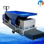
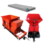
После завершения и проверки монолитного каркаса начинается основной этап работ: монтаж сборных бетонных стеновых панелей и перекрытий. Стеновые панели и перекрытия, используемые в данном технологическом процессе, изготавливаются серийно на специализированном промышленном оборудовании — а экструдер для сборных бетонных стеновых панелей и машина для производства сборных железобетонных панелей — которые заменяют традиционный трудоемкий подход, предполагающий ручную установку опалубки и изготовление монолитных элементов на строительной площадке. Это значительно повышает точность и скорость производства элементов, позволяя при этом контролировать отходы материалов и затраты на рабочую силу, что создает основу для более быстрого и экономичного строительства.
Примечание по структуре: в данном рабочем процессе монолитные колонны и балки каркаса составляют основной несущий каркас — они возводятся в первую очередь и принимают на себя весовые и поперечные нагрузки здания. Сборные стеновые панели — это ненесущие заполняющие/ограждающие элементы впоследствии устанавливаются в готовый каркас, в то время как сборные перекрытия являются несущими элементами, непосредственно опирающимися на балки каркаса. Именно такое распределение функций и делает экструдер для сборных бетонных стеновых панелей подходящий инструмент для данной задачи: формование методом непрерывной экструзии наилучшим образом подходит для полых легких стеновых панелей, не требующих конструктивного армирования большого диаметра или тяжелых заделанных соединительных элементов, что как раз и относится к заполняющим панелям, устанавливаемым внутри уже несущего каркаса. Их соединения с каркасом должны выдерживать лишь собственный вес и внеплоскостные ветровые/сейсмические нагрузки, а также нагрузки, возникающие при монтаже — а не сейсмические соединения с втулками или цементным раствором, требуемые для несущих сборных сдвиговых стен (см. раздел 8, где приведены стандарты, охватывающие этот отдельный случай применения, актуальный только в том случае, если в проекте несущие монолитные каркасы заменяются сборными несущими стенами).
Все сборные элементы изготавливаются на оборудовании в рамках единого интегрированного технологического процесса, проходят паровую обработку и испытания на прочность перед транспортировкой на строительную площадку для подъема и монтажа, что обеспечивает их точные размеры, стабильную прочность и высокую однородность. Монтаж строго выполняется в следующей последовательности: “стеновые панели перед перекрытиями, внутренние стены перед наружными”, что обеспечивает упорядоченную установку элементов с разумным распределением нагрузок и надежными соединениями.
6.1 Подготовка к установке
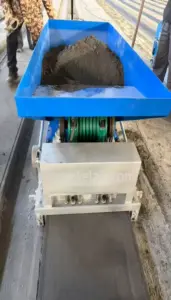
До того как компоненты поступят на строительную площадку, необходимо проверить качество стеновых панелей и перекрытий, изготовленных компанией экструдер для сборных бетонных стеновых панелей и машина для производства сборных железобетонных панелей, проверяя технические характеристики, размеры, прочность и качество поверхности. Обе машины работают в режиме механизированного конвейерного производства: экструдер для стеновых панелей может за один интегрированный проход выполнить распределение бетона, экструзионное формование и вибрацию/уплотнение, производя панели с равномерной плотностью и минимальными отклонениями в размерах; машина для изготовления сборных бетонных панелей может быть настроена на индивидуальную толщину плит перекрытия и схему армирования в соответствии с требованиями проекта, обеспечивая высокую эффективность серийного производства. По сравнению с традиционным методом изготовления сборных конструкций это позволяет существенно сократить отходы материала и затраты на рабочую силу.
При полуке груза осмотрите панели и плиты на наличие поверхностных трещин, сколов по краям и углам или деформаций, а также убедитесь, что встроенные детали и соединительные отверстия расположены правильно. Укладывайте элементы по типам на выровненную и уплотненную площадку для хранения с использованием деревянной подкладки — стеновые панели следует хранить вертикально, а плит перекрытия — горизонтально — чтобы предотвратить их раздавливание или повреждение.
Одновременно с этим необходимо очистить строительную площадку, повторно проверить высотные отметки и заново разметить осевые линии. Разметьте линии установки и высотные контрольные линии для стеновых панелей и плит перекрытия в местах расположения соответствующих колонн и балок каркаса, а также установите выравнивающие прокладки для обеспечения точной отправной точки монтажа. Заранее проверьте и откалибруйте кран, подъемные стропы и инструменты для выравнивания, а также примите меры безопасности.
6.2 Монтаж сборных стеновых панелей
Стеновые панели поднимаются с помощью многоточечной крановой установки. Точки подъема выбираются с учетом центра тяжести панели, чтобы обеспечить равномерное распределение нагрузки и предотвратить деформацию или появление трещин во время подъема. После того как панель поднята над местом установки, её медленно опускают, а рабочие точно выравнивают её, корректируя положение, вертикальность и горизонтальность по контрольным линиям.
После первоначальной установки закрепите панель временными раскосами, расположенными на равном расстоянии друг от друга, чтобы обеспечить её устойчивость и предотвратить опрокидывание. Незамедлительно скорректируйте вертикальность и ширину стыков, чтобы смежные панели были выровнены с одинаковыми, ровными зазорами. После корректировки соедините панель с монолитным каркасом с помощью встроенных соединительных элементов — стандартным является сварное или болтовое крепление, соответствующий строительным нормам, поскольку панель является ненесущим заполняющим элементом, удерживаемым уже готовым несущим каркасом, а не конструктивной сдвиговой стеной, — чтобы зафиксировать окончательное положение панели.
После того как все стеновые панели будут установлены и закреплены, очистите стыки между панелями, а также между панелями и каркасом, а затем заделайте их специальным раствором или бетоном с мелким заполнителем, тщательно уплотнив, чтобы обеспечить целостность, герметичность и водонепроницаемость стеновой конструкции.
6.3 Установка сборных перекрытий
После того как стеновые панели установлены, закреплены, а соединительные швы приобрели достаточную прочность, приступают к укладке перекрытий. Плиты поднимаются с помощью сбалансированной многоточечной подъемной рамы, плавно поднимаются и опускаются, чтобы избежать ударов или раскачивания, которые могут повредить элементы конструкции или сместить стеновые панели. Плиты укладываются строго в соответствии с чертежами разметки, опираясь на верхнюю часть балок каркаса или несущие стеновые панели с постоянной длиной опоры, соответствующей нормам.
После укладки отрегулируйте расстояние между плитами, их высоту и ровность так, чтобы поверхность пола была ровной, а ширина швов — одинаковой. В местах соединения «плита-плита» и «плита-каркас» закрепите и приварите заделанную арматуру, соединив выступающие стержни плиты с арматурой каркасных балок и стеновых панелей, что усилит интеграцию пола с общей конструкцией. Заполните швы бетоном с мелким заполнителем послойно, тщательно уплотняя и вибрируя, а затем незамедлительно проведите отверждение, чтобы предотвратить растрескивание швов.
6.4 Совместная обработка и приемка по качеству
После завершения монтажа всех стеновых панелей и плит перекрытия необходимо тщательно проверить положение, высоту, вертикальность и ровность элементов, а также качество сварных швов, длину анкерных стержней и плотность заделки цементного раствора в каждом соединительном шве, чтобы убедиться в прочности и надежности соединений. Незамедлительно устраните все отклонения при монтаже и проведите полную самостоятельную проверку конструкции и повторный осмотр. Только после прохождения приемочных испытаний можно приступать к укладке кровли, внутренней отделке и другим последующим работам.
7. Основные этапы контроля качества
- Подготовительный этап: строго контролировать соотношение смеси из извести и грунта 3:7, толщину слоя и количество проходов уплотнителя; проверять степень уплотнения по всей площади с помощью документированного метода (кольцевой резак/замена песка/ядерная плотность) для устранения риска образования мягкого основания или недостаточного уплотнения и предотвращения осадки на этапе строительства.
- Этап устройства фундамента и каркаса: строго контролировать размеры арматуры, расстояние между арматурными стержнями и длину закрепления; надежно закрепить раскосы опалубки; тщательно уплотнять бетон во время заливки, чтобы предотвратить образование сотовых дефектов, язв или пустот; строго соблюдать процедуры выдержки бетона для обеспечения достижения расчетной прочности.
- Этап монтажа сборных элементов: тщательно проверяйте элементы при поступлении; соблюдайте стандартные процедуры подъема, чтобы предотвратить повреждения; точно выравнивайте элементы, строго контролируйте отклонения по вертикальности и плоскостности, а также убедитесь, что стыковые соединения и затирка полностью уплотнены и надежно закреплены, чтобы обеспечить общую жесткость и устойчивость конструкции.
- Контроль за сдачей этапов: строго соблюдать принцип, согласно которому “следующий этап не начинается до тех пор, пока предыдущий этап не пройдет приемку”, с ведением документально зафиксированных протоколов приемки скрытых работ на каждом этапе для обеспечения контроля качества на протяжении всего строительства.
8. Применимые стандарты и нормативы, на которые следует ссылаться
Для обеспечения технически обоснованной строительной документации каждый из вышеуказанных этапов следует сверить с соответствующими национальными или региональными нормами и правилами, например (ссылки, относящиеся к Китаю, — при необходимости заменить на местные эквиваленты):
- Нормативный документ по приёмке качества строительства бетонных конструкций (GB 50204)
- Нормы по проектированию фундаментов зданий (GB 50007)
- Нормы по сейсмостойкому проектированию зданий (GB 50011)
- Технические условия на сборные железобетонные конструкции (JGJ 1) и Технический стандарт на сборные здания с железобетонным каркасом (GB/T 51231) — применимы в первую очередь в случае использования несущих сборных стеновых панелей вместо монолитного каркаса; не требуются для ненесущих заполняющих панелей, описанных в разделе 6
- Строительные нормы и правила по устройству фундаментов зданий / Технические условия по обработке грунта (JGJ 79)
При реализации проектов за пределами Китая следует применять признанные на местном уровне эквивалентные стандарты (например, руководства ACI 318 / PCI по проектированию и строительству в США или Еврокод 2 в ЕС) в отношении требований к проектированию бетонных конструкций, их отработке и соединению сборных элементов.
9. Преимущества использования экструдера для производства сборных железобетонных стеновых панелей и машины для изготовления панелей
- Ускорение производства: непрерывная механизированная формовка позволяет значительно сократить время, затрачиваемое на ручную установку опалубки, резку панелей и изготовление плит.
- Более высокая точность размеров: контролируемые машиной распределение, формовка и вибрация позволяют снизить отклонения в размерах по сравнению с ручным монолитным бетонированием на месте.
- Снижение отходов материала и затрат на рабочую силу: точное дозирование и автоматизированное формование позволяют сократить излишки бетона и количество часов ручного труда.
- Стабильное качество: обработка паром и контроль прочности на линии производства обеспечивают каждой панели и плите сопоставимую прочность и плотность.
- Более быстрый и экологичный монтаж на объекте: готовые заводские компоненты позволяют сократить объем влажных работ на строительной площадке, что ускоряет общие сроки строительства и снижает объем строительных отходов.
10. Часто задаваемые вопросы
Для чего используется экструдер для производства сборных железобетонных стеновых панелей?
A экструдер для сборных бетонных стеновых панелей механизирует производство стеновых панелей — распределение бетона, его экструдирование в нужную форму, а также вибрацию и уплотнение за один непрерывный проход. Она идеально подходит для производства полых легких стеновых панелей, которые служат ненесущими заполняющими или ограждающими стенами внутри уже готового несущего каркаса, возведенного методом монолитного бетонирования, что именно и соответствует роли стеновых панелей в данной последовательности строительства (сначала возводится каркас, а затем устанавливаются панели).
Для чего используется машина для изготовления сборных железобетонных панелей?
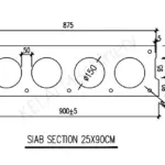
A машина для производства сборных железобетонных панелей (часто используется для изготовления перекрытий) позволяет изготавливать элементы заданной толщины и с заданной схемой армирования, что обеспечивает крупносерийное и стабильное производство сборных перекрытий для малоэтажного жилья и небольших коммерческих зданий.
Какова типичная последовательность этапов строительства дома из сборного железобетона?
Выравнивание площадки и уплотнение известково-грунтового слоя, затем возведение столбовых фундаментов и фундаментных балок, далее монолитное заливание колонн и балок каркаса и, наконец, монтаж сборных стеновых панелей и перекрытий — каждый этап проходит проверку перед началом следующего.
Подходит ли этот метод для многоэтажных зданий?
Как уже упоминалось, данный технологический процесс предназначен для малоэтажных зданий. При возведении многоэтажных зданий из сборных конструкций каркас и сборные элементы обычно монтируются поэтажно, а не сначала возводится весь каркас целиком; при этом необходимо соблюдать стандарты, касающиеся сборных конструкций, указанные в разделе 8.
11. Заключение
Описанный здесь поэтапный метод строительства — подготовка участка и фундамента → возведение фундамента → возведение каркаса методом монолитного бетонирования → монтаж сборных элементов — соответствует практической логике строительства с использованием сборных бетонных стеновых панелей и перекрытий. Основано на возможностях промышленного производства, обеспечивающих прочность экструдер для сборных бетонных стеновых панелей и машина для производства сборных железобетонных панелей, а также благодаря сочетанию преимуществ монолитного строительства и сборных элементов данный подход обеспечивает устойчивость и сейсмостойкость фундамента и несущего каркаса, в то время как механизированное производство сборных элементов существенно повышает производительность, позволяет экономить материалы и трудозатраты, а также обеспечивает эффективность, энергосбережение и экологические преимущества монтажа на строительной площадке.
На каждом этапе строительства четко распределены обязанности, и каждый этап тесно связан со следующим; благодаря тщательному управлению подготовкой строительной площадки, уплотнением известково-грунтовой смеси, монолитным бетонированием колонн и балок, механизированным производством сборных элементов, а также подъемом и монтажом строители могут повысить качество жилых домов из сборного железобетона, снизить строительные риски, сократить сроки строительства и контролировать затраты.
Данный строительный процесс хорошо подходит для нужд малоэтажного жилищного строительства, обеспечивает четкую и практичную организацию рабочего процесса и соответствует тенденции развития отрасли в направлении экологичного, индустриализированного строительства, представляя собой практическое техническое руководство, основанное на стандартах, для аналогичных проектов строительства жилья из сборного железобетона.
Китай сборный бетон забор стены делая машину производитель | Kelai машины