Hausbau mit Betonfertigteilwänden und -decken: Ein umfassender Leitfaden zum gesamten Bauprozess
Zusammenfassung
Betonfertigteil-Wandplatten und -Deckenplatten sind die Kernkomponenten von Fertigteilhaus aus Beton, die die Vorteile einer industrialisierten Fertigung, einer schnellen Montage vor Ort, Energieeffizienz und hoher struktureller Stabilität bieten. Im Vergleich zu herkömmlichen, vollständig vor Ort gegossenen Gebäuden reduzieren Häuser aus Betonfertigteilen den Nassbau vor Ort erheblich, verkürzen die Bauzeit, verringern den Bauschutt und gewährleisten standardisierte, normkonforme Bauteile. Dieser Leitfaden führt durch einen vollständigen, in der Praxis erprobten Bauablauf – Geländeglättung und Fundamentvorbereitung, Errichtung der Fundamentkonstruktion, Ortbeton-Rahmenstützen und -träger sowie Einbau von vorgefertigten Wandplatten und Deckenplatten – und erläutert, wie ein Extruder für Betonfertigteil-Wandplatten und eine Maschine zur Herstellung von Betonfertigteilplatten werden in jeder Bauphase eingesetzt. Außerdem werden die technischen Kontrollpunkte und Qualitätsstandards beschrieben, die für die Errichtung eines sicheren, vorschriftsmäßigen Niedrigbauhauses aus Betonfertigteilen erforderlich sind.
1. Einleitung: Warum der Fertigteilbau an Bedeutung gewinnt
Da sich die Industrialisierung des Bauwesens weltweit beschleunigt, entwickelt sich die vorgefertigte (montierte) Bauweise zu einem zentralen Ansatz für den ökologischen und CO₂-armen Wandel der Branche. Betonfertigteil-Wandplatten und -Deckenplatten werden unter standardisierten Werksbedingungen hergestellt, bis zur endgültigen Festigkeit ausgehärtet und anschließend zur Montage auf die Baustelle transportiert – in Kombination mit vor Ort gegossenen Rahmenelementen sorgt dieser hybride Ansatz für ein ausgewogenes Verhältnis zwischen struktureller Integrität, Stabilität und Baugeschwindigkeit. Er findet breite Anwendung bei selbstgebauten Häusern in ländlichen Gebieten, niedrigen Bürogebäuden und kleinen Nebengebäuden.
Die traditionelle Vollortbetonbauweise ist mit hohem Arbeitsaufwand vor Ort, langen Bauzeiten, Wetterabhängigkeit und uneinheitlicher Qualitätskontrolle verbunden. Die Montage von Betonfertigteilen – bei der die Bauteile vorgefertigt und die Module vor Ort zusammengebaut werden, kombiniert mit einem Ortbetonfundament und -rahmen – gleicht die begrenzte Gesamtsteifigkeit rein vorgefertigter Konstruktionen wirksam aus. Dieser Leitfaden folgt Schritt für Schritt dem natürlichen Bauablauf, von der Fundamentvorbereitung bis zum Einbau der Betonfertigteile, und erläutert die Logik sowie die wichtigsten Kontrollpunkte jeder Bauphase, um sowohl die Bauqualität als auch die Tragwerkssicherheit zu gewährleisten.
Anmerkung zum Geltungsbereich: Der folgende Arbeitsablauf wurde verfasst für Niedrige (in der Regel 1–3-stöckige) Wohn- und kleinere Geschäftsgebäude. Bei mehrgeschossigen Fertigteilkonstruktionen werden der Rahmen und die Fertigteile in der Regel Etage für Etage in einer fortlaufenden Abfolge montiert, anstatt den gesamten Rahmen fertigzustellen, bevor die Platten eingebaut werden; Leser, die an mehrgeschossigen Projekten arbeiten, sollten die Abfolge entsprechend anpassen und die örtlichen Normen für Fertigteilkonstruktionen befolgen (siehe die Verweise auf die Bauvorschriften in Abschnitt 8).
2. Allgemeiner Ablauf der Bauarbeiten
Diese Bauweise kombiniert eine Ortbetonfundament, Ortbeton-Rahmensäulen und -träger sowie Montage von Fertigbauteilen. Ausgehend vom tragtechnischen Verhalten und den Bauvorschriften lautet die Reihenfolge der Kernschritte wie folgt:
- Geländeausgleich, Fundamentaushub und schichtweise Verdichtung von Kalk-Erde im Verhältnis 3:7
- Bau von Pfahlfundamenten und Fundamentbalken
- Rahmenkonstruktion aus Ortbeton mit Stützen und Trägern
- Einbau von Betonfertigteil-Wandelementen und -Deckenplatten
Jede Bauphase ist eng mit der nächsten verknüpft: Die vorhergehende Bauphase muss die Abnahme bestehen, bevor die nächste Bauphase beginnen kann. Dadurch werden eine stabile Grundlage, ein gerader Rahmen, die präzise Montage der Bauteile sowie die allgemeine Sicherheit und Langlebigkeit des Bauwerks gewährleistet.
3. Geländeglättung, Aushub und Verdichtung einer Kalk-Erde-Mischung im Verhältnis 3:7
Das Fundament bildet die tragende Basis des Hauses. Die Qualität der Baustellenvorbereitung und der Verdichtung der Kalk-Erd-Mischung bestimmt unmittelbar die Gesamtstabilität und trägt dazu bei, spätere Setzungen, Risse und Schräglagen zu verhindern – damit ist dies die erste entscheidende Bauphase. Sie umfasst drei Teile: die Nivellierung des Baugeländes, den Aushub der Baugrube und die schichtweise Verdichtung der Kalk-Erd-Mischung.
3.1 Geländeglättung
Legen Sie vor Baubeginn mithilfe einer Totalstation und einer Wasserwaage die Höhen- und Achsenkontrolllinien auf der Grundlage der Bauzeichnungen und der Geländetopografie fest und definieren Sie dabei die Gebäudegrenze, den Aushubbereich und die Arbeitszonen. Entfernen Sie Vegetation, Schlamm, Bauschutt und weichen Oberboden, damit die Arbeitsfläche sauber und fest ist. Verwenden Sie einen Bagger mit manueller Feinarbeit, um das Gelände auf die geplante Neigung zu planieren. Stellen Sie dabei einen reibungslosen Wasserabfluss sicher und verhindern Sie, dass sich Regenwasser ansammelt und den Baugrund durchnässt. Führen Sie nach der Planierung eine vorläufige Verdichtung durch, um die Gesamtdichte des Geländes zu verbessern und eine ebene Arbeitsfläche für Aushub- und Kalk-Boden-Arbeiten vorzubereiten.
3.2 Aushub der Baugrube
Legen Sie die Aushubtiefe und -breite anhand der Fundamentplanung und der örtlichen geologischen Gegebenheiten fest und befolgen Sie dabei das Prinzip “schichtweiser Aushub, kein Überaushub”. Führen Sie den Großteil der Arbeiten mit mechanischen Aushubverfahren durch und wechseln Sie erst in den letzten 20–30 cm über der geplanten Sohlenhöhe zum manuellen Aushub, um den ungestörten Untergrund nicht zu beeinträchtigen und dessen Tragfähigkeit nicht zu verringern. Überprüfen Sie während der Aushubarbeiten kontinuierlich die Achsenlinien, die Höhe und die Neigung der Baugrube und entfernen Sie unverzüglich losen Boden und stehendes Wasser. Nach Abschluss der Aushubarbeiten ist die untere Bodenschicht zu untersuchen; sollten weicher Boden oder Hohlräume festgestellt werden, sind diese zu melden und durch Bodenaustausch oder Verdichtung zu behandeln, um die Tragfähigkeit auf das in der Planung geforderte Niveau zu bringen.
3.3 Verdichtung einer 3:7-Kalk-Boden-Schicht
Sobald die Baugrube die Prüfung bestanden hat, füllen Sie eine Kalk-Erd-Mischung im Verhältnis 3:7 ein (ein Volumenverhältnis von 3:7 zwischen Kalkhydrat und normaler Erde) – ein gängiges Material zur Fundamentverstärkung, das wegen seiner hohen Festigkeit, geringen Verdichtbarkeit und guten Stabilität geschätzt wird. Sieben Sie den Boden zuvor, um Steine und Fremdkörper zu entfernen, und halten Sie den Feuchtigkeitsgehalt im optimalen Bereich, damit die Kalk-Erde-Mischung eine gleichmäßige Farbe aufweist und weder Streifen noch Klumpen bildet.
Den Kalkboden schichtweise auftragen und verdichten, wobei jede lose Schicht eine Dicke von 20–30 cm aufweisen sollte und mit einem Froschstampfer oder einer Walze in mindestens drei Durchgängen verdichtet wird. Wenden Sie eine gleichmäßige Verdichtungskraft an und prüfen Sie den Verdichtungsgrad nach jeder Schicht; Die Verdichtung muss ≥95% der maximalen Trockendichte erreichen (Überprüfung mittels Ring-Cutter-Verfahren, Sandersatzverfahren oder nuklearem Dichtemessgerät gemäß der geltenden lokalen Prüfnorm) vor dem Einbau der nächsten Schicht. Sobald die Kalk-Erd-Schicht die vorgesehene Untergrundhöhe erreicht hat, ist die Oberfläche zu nivellieren und auszuhärten – während der Aushärtung darf kein Fahrzeugverkehr stattfinden und es dürfen keine Lasten aufgeschichtet werden –, damit die Kalk-Erd-Schicht stetig an Festigkeit gewinnt und eine tragfähige Unterlage für die nachfolgende Fundamentkonstruktion bildet.
4. Bau von Säulenfundamenten und Fundamentträgern
Sobald die Kalk-Erd-Grundschicht ordnungsgemäß ausgehärtet ist, beginnt der Bau der Fundamentkonstruktion. Säulenfundamente und Fundamentträger verbinden den Boden mit der darüberliegenden Rahmenkonstruktion – sie nehmen die Lasten des Gebäudes auf, leiten sie gleichmäßig in den Boden weiter und verhindern Verformungen des Fundaments, während sie gleichzeitig die allgemeine strukturelle Integrität stärken. Dies ist die entscheidende Übergangsphase zwischen Fundament und Überbau.
4.1 Layout und Vorbereitung des Untergrunds
Legen Sie anhand der Achsenkontrollpunkte des Gebäudes die Lage-, Kanten- und Höhenkontrolllinien für Säulenfundamente und Fundamentträger präzise fest und kennzeichnen Sie diese deutlich mit Tintenstrichen. Reinigen und ebnen Sie die Oberfläche des Kalk-Erd-Untergrunds, entfernen Sie losen Staub und Schmutz und befeuchten Sie die Oberfläche, damit der Beton fest mit dem Untergrund haftet und sich keine Hohlräume oder Risse bilden.
4.2 Einbau der Bewehrung und Schalung
Die Bewehrung für Fundament und Fundamentträger ist gemäß den Konstruktionszeichnungen herzustellen, wobei Stabdurchmesser, Abstand und Verankerungslänge streng einzuhalten sind; die Staboberflächen müssen rost- und ölfrei sein. Zuerst ist die Fundamentbewehrung einzubauen, wobei die Hauptstäbe und Bügel so zu befestigen sind, dass der Bewehrungskorb exakt positioniert und fest verbunden ist; anschließend ist die Fundamentbalkenbewehrung einzubauen, wobei auf durchgehende Stäbe, normgerechte Überlappungslängen und eine geordnete Anordnung der Stäbe an den Verbindungsknoten ohne Überfüllung oder Fehlausrichtung zu achten ist. Nach dem Verbinden sind Abstandhalter für die Betondeckung anzubringen, um eine gleichmäßige Dicke der Schutzschicht zu gewährleisten.
Nach der Überprüfung der Bewehrung ist die Schalung – aus Stahl oder hochfesten Holzplatten – mit dichten Fugen und ohne Lücken oder Verformungen anzubringen; sie ist mit Stahlrohren und Holz zu verstreben, um der Schalung ausreichende Steifigkeit und Stabilität zu verleihen und ein Ausbeulen oder das Austreten von Mörtel während des Betonierens zu verhindern. Überprüfen Sie nach der Montage der Schalung erneut die Abmessungen, die Höhe und die Lage des Fundaments anhand der Konstruktionsunterlagen.
4.3 Betonieren und Aushärten
Den Beton in der vorgesehenen Festigkeitsklasse als Fertigbeton oder vor Ort gemischt einbringen. Den Beton schichtweise einbringen und mit einem Eintauchrüttler verdichten, um Luftporen zu entfernen und eine hohe Dichte zu gewährleisten, wobei Wabenbildung, Vertiefungen oder Hohlräume zu vermeiden sind. Säulenfundamente und Fundamentträger sollten, soweit möglich, in einem Arbeitsgang durchgehend gegossen werden, um Baufugen zu minimieren und die strukturelle Integrität zu gewährleisten.
Nach dem Einbringen ist die Oberfläche unverzüglich zu glätten und zu nivellieren; sobald der Beton die Erstabbindung erreicht hat, ist mit der Wasseraushärtung für mindestens 7 Tage zu beginnen (je nach Umgebungstemperatur und geltender Aushärtungsnorm anzupassen), wobei die Oberfläche während der gesamten Zeit feucht gehalten und nicht gestört werden darf, damit sich die Festigkeit des Fundamentbetons als Untergrund für die darüber liegende Rahmenkonstruktion gleichmäßig entwickelt.
5. Vor Ort gegossene Betonrahmenstützen und -träger
Sobald die Fundamentkonstruktion mindestens 70% ihrer Auslegungsfestigkeit (28-Tage-Festigkeit) erreicht hat – was anhand von unter gleichen Bedingungen ausgehärteten Prüfkübeln/-zylindern überprüft wird, wobei das genaue Alter von der Betonklasse und der Umgebungstemperatur abhängt –, beginnt der Bau der oberen, vor Ort gegossenen Rahmenstützen und -träger. Der Rahmen bildet das tragende Skelett des Oberbaus: Er nimmt die von den Wandelementen und Deckenplatten übertragenen Lasten auf, verankert die Fertigteilelemente und erhöht die Gesamtsteifigkeit sowie die Erdbebensicherheit. Ein vor Ort gegossener Rahmen gleicht die verminderte Kontinuität an den Fugen der Fertigteilelemente wirksam aus und verbessert so die allgemeine Tragwerkssicherheit.
5.1 Vertikale Anordnung und Vorbereitung des Untergrunds
Tragen Sie auf der Oberseite des Fundaments die Achsen und Lageabmessungen für die Rahmenstützen und -träger präzise ein und zeichnen Sie Kontrolllinien an. Rauen Sie die Betonkontaktfläche auf der Oberseite des Fundaments auf, entfernen Sie Zementschleier und losen Beton, reinigen Sie die Fläche anschließend und befeuchten Sie sie, um die Haftung zwischen neuem und altem Beton zu verbessern und Ablösungsrisse zu verhindern.
5.2 Bewehrung von Stützen und Trägern im Rahmenbau
Gemäß den Zeichnungen sind die vertikalen Säulenbewehrungen zu überlappen und zu verbinden, wobei auf Senkrechte und Abstand zu achten ist; der Abstand der Bügel in verschlüsselten und nicht verschlüsselten Zonen sowie die Überlappungs- und Verankerungslängen müssen die seismischen Anforderungen der Konstruktion strikt erfüllen. Nachdem die Säulenbewehrung die Abnahme bestanden hat, sind das Trägerstützgerüst und die Trägerschalung am Unterzug zu errichten; anschließend ist die Trägerbewehrung zu verbinden, wobei sicherzustellen ist, dass die Bewehrung an den Träger-Säulen-Verbindungen ordnungsgemäß angeordnet und fest verbunden ist, sodass ein vollständiger tragender Bewehrungskorb entsteht.
5.3 Einbau und Abstützung der Schalung
Nachdem die Bewehrung die Prüfung bestanden hat, ist die Seitenschalung für Stützen und Träger anzubringen. Die Schalung muss bündig sein, fest miteinander verbunden und gegen das Austreten von Fugenmörtel abgedichtet sein. Die Säulenschalung ist mit Klammern und Stahlrohrstützen abzustützen, um die Lotrechtigkeit zu gewährleisten; die Trägerschalung ist mit einem System aus Stützen, Querstreben und Hebeböcken abzustützen, wobei die Stützabstände streng kontrolliert werden müssen, damit das System das Eigengewicht des Betons und die Baulasten sicher tragen kann, ohne sich zu verformen oder abzusacken. Überprüfen Sie nach der Montage die Abmessungen, die Höhe, die Lotrechtigkeit und die Stabilität der Schalung vollständig.
5.4 Betonieren, Rütteln und Aushärten
Den Beton für Rahmenstützen und -träger schichtweise einbringen: Zuerst die Stützen einbringen und verdichten; sobald der Beton der Stützen die Höhe der Trägerunterseite erreicht hat, kurz pausieren, bevor die Träger eingebringt werden, um eine dichte Verbindung an den Stützen-Träger-Anschlussstellen zu gewährleisten. Vermeiden Sie während des Verdichtens den Kontakt mit Bewehrung und Schalung, um eine Verschiebung der Stäbe oder eine Verformung der Schalung zu verhindern. Nach dem Einbringen unverzüglich glätten und nivellieren sowie die Höhen der Bauteile markieren.
Beginnen Sie mit der Wasseraushärtung, sobald der Beton seine Endfestigkeit erreicht hat; decken Sie ihn bei heißem Wetter mit Geotextil ab, um die Feuchtigkeit zu bewahren, und bringen Sie bei kaltem Wetter einen Schutz gegen Kälte auf, wobei die Aushärtungszeit mindestens 7 Tage betragen muss. Schalung und Abstützung dürfen erst entfernt werden, wenn der Rahmenbeton die für die Aufnahme der Lasten der Fertigteilelemente erforderliche Festigkeit erreicht hat – danach beginnt der Einbau der Fertigteilelemente.
6. Einbau von Betonfertigteilwänden und -deckenplatten
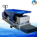
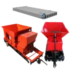
Sobald der Ortbetonrahmen fertiggestellt und abgenommen ist, beginnt der Kernbau: die Montage der vorgefertigten Betonwandelemente und Deckenplatten. Die in diesem Arbeitsablauf verwendeten Wandelemente und Deckenplatten werden in Serie auf speziellen Industrieanlagen hergestellt – ein Extruder für Betonfertigteil-Wandplatten und eine Maschine zur Herstellung von Betonfertigteilplatten — die den herkömmlichen, arbeitsintensiven Ansatz der manuellen Schalung und des Vor Ort gegossenen Fertigteils ersetzen. Dies verbessert die Genauigkeit und Geschwindigkeit der Bauteilfertigung erheblich und sorgt gleichzeitig für eine Reduzierung von Materialverschwendung und Arbeitskosten, wodurch die Grundlage für eine schnellere und kostengünstigere Bauausführung geschaffen wird.
Anmerkung zur Strukturlogik: In diesem Arbeitsablauf ist die Vor Ort gegossene Rahmenstützen und -träger bilden das tragende Hauptgerüst — sie werden zuerst errichtet und nehmen die Schwerkraft- und Querkräfte des Gebäudes auf. Die vorgefertigten Wandplatten sind nichttragende Ausfachungs-/Umschlusselemente die anschließend in den fertigen Rahmen eingebaut werden, während die vorgefertigten Deckenplatten tragende Bauteile sind, die direkt auf den Rahmenbalken aufliegen. Genau diese Rollenverteilung macht das Extruder für Betonfertigteil-Wandplatten Das richtige Werkzeug für die Aufgabe: Die kontinuierliche Extrusionsformung eignet sich am besten für hohlkernige, leichte Wandplatten, die keine strukturelle Bewehrung mit großem Durchmesser oder schwere, eingebettete Verbindungselemente erfordern – was genau auf Füllplatten zutrifft, die in einem bereits tragenden Rahmen sitzen. Ihre Verbindungen zum Rahmen müssen lediglich dem Eigengewicht sowie Wind- und Erdbebenlasten außerhalb der Ebene und den Belastungen während der Bauarbeiten standhalten – nicht den Erdbebenhülsen- oder Mörtelüberlappungsverbindungen, die für tragende vorgefertigte Schubwände erforderlich sind (siehe Abschnitt 8 für Normen zu diesem separaten Anwendungsfall, der nur relevant ist, wenn bei einem Projekt tragende Fertigteil-Scherwände anstelle des Ortbetonrahmens verwendet werden).
Alle Fertigteilkomponenten werden auf den Anlagen in einem integrierten Prozess geformt, dampfgehärtet und einer Festigkeitsprüfung unterzogen, bevor sie zur Baustelle transportiert werden, um dort montiert zu werden. Dadurch weisen sie präzise Abmessungen, stabile Festigkeit und eine hohe Gleichmäßigkeit auf. Bei der Montage wird strikt die Reihenfolge “Wandplatten vor Deckenplatten, Innenwände vor Außenwänden” eingehalten, wodurch sichergestellt wird, dass die Bauteile geordnet mit sinnvollen Lastwegen und sicheren Verbindungen eingebaut werden.

6.1 Vorbereitungen vor der Installation
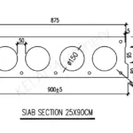
Bevor die Bauteile auf der Baustelle eintreffen, überprüfen Sie die Qualität der Wandpaneele und Bodenplatten, die von der Extruder für Betonfertigteil-Wandplatten und Maschine zur Herstellung von Betonfertigteilplatten, wobei Spezifikationen, Abmessungen, Festigkeit und Oberflächenbeschaffenheit geprüft werden. Beide Maschinen arbeiten im mechanisierten Fließbandbetrieb: Der Wandplatten-Extruder kann die Betonverteilung, die Extrusionsformung sowie die Rüttelung und Verdichtung in einem einzigen integrierten Arbeitsgang durchführen und so Platten mit gleichmäßiger Dichte und minimalen Maßabweichungen herstellen; die Maschine zur Herstellung von Betonfertigteilplatten lässt sich auf kundenspezifische Bodenplattenstärken und Bewehrungsanordnungen konfigurieren, um den Projektanforderungen gerecht zu werden, und bietet dabei eine hohe Effizienz in der Serienfertigung. Im Vergleich zum herkömmlichen Fertigteilbau werden dadurch Materialverschwendung und Arbeitskosten erheblich reduziert.
Überprüfen Sie die Platten und Elemente nach Erhalt auf Oberflächenrisse, abgesplitterte Kanten oder Ecken sowie Verformungen und vergewissern Sie sich, dass Einbauteile und Befestigungslöcher korrekt positioniert sind. Stapeln Sie die Bauteile nach Typ auf einer ebenen, verdichteten Lagerfläche mit Holzunterlage – Wandplatten senkrecht, Bodenplatten waagerecht –, um ein Zusammendrücken oder Beschädigungen zu vermeiden.
Gleichzeitig ist die Baustelle zu reinigen, die Höhenangaben erneut zu überprüfen und die Achsenlinien neu zu markieren. Markieren Sie die Montage- und Höhenkontrolllinien für Wandpaneele und Bodenplatten an den entsprechenden Positionen der Rahmenstützen und -träger und bringen Sie Höhenausgleichsscheiben an, um einen genauen Montagebezugspunkt zu gewährleisten. Überprüfen und kalibrieren Sie den Kran, die Hebegurte und die Ausrichtungswerkzeuge im Voraus und treffen Sie entsprechende Sicherheitsvorkehrungen.
6.2 Einbau von vorgefertigten Wandelementen
Die Wandpaneele werden mit einer Mehrpunkt-Kranvorrichtung angehoben. Die Hebepunkte werden entsprechend dem Schwerpunkt des Paneels festgelegt, um eine gleichmäßige Lastverteilung zu gewährleisten und Verformungen oder Risse während des Hebevorgangs zu vermeiden. Sobald das Paneel über seine Einbauposition angehoben ist, wird es langsam abgesenkt, während die Arbeiter es präzise ausrichten und dabei Position, Lotrechtigkeit und Waagheit anhand der Kontrolllinien anpassen.
Befestigen Sie die Platte nach dem ersten Einbau mit provisorischen Verstrebungen in gleichmäßigen Abständen, um sie zu stabilisieren und ein Umkippen zu verhindern. Korrigieren Sie umgehend die Lotrechtigkeit und die Fugenbreite, damit angrenzende Platten mit einheitlichen, gleichmäßigen Fugen aneinandergereiht sind. Nach der Korrektur verbinden Sie die Platte über ihre eingebetteten Verbindungselemente mit dem Ortbetonrahmen – dabei ist eine Verankerung durch Schweißen oder Verschrauben der Standard, der hier vorschriftsmäßige Ansatz, da es sich bei der Platte um ein nichttragendes Ausfachungselement handelt, das von einem bereits fertiggestellten tragenden Rahmen gehalten wird und keine tragende Schubwand darstellt – um die endgültige Position der Platte zu fixieren.
Sobald alle Wandpaneele montiert und befestigt sind, reinigen Sie die Fugen zwischen den Paneelen sowie zwischen den Paneelen und dem Rahmen und versiegeln Sie diese anschließend mit Spezialfugenmörtel oder Feinbeton, der vollständig verdichtet wird, um die Integrität, Luftdichtheit und Wasserbeständigkeit der Wandkonstruktion zu gewährleisten.
6.3 Einbau von Fertigdeckenplatten
Sobald die Wandpaneele montiert und befestigt sind und die Verbindungsstellen eine ausreichende Festigkeit erreicht haben, beginnt die Verlegung der Bodenplatten. Die Deckenplatten werden mit einem ausgewuchteten Mehrpunkt-Hebegestell angehoben und sanft angehoben und abgesenkt, um Stöße oder Schwingungen zu vermeiden, die Bauteile beschädigen oder die Wandpaneele verschieben könnten. Die Deckenplatten werden streng nach den Lageplänen verlegt und aufliegen dabei auf den Obergurten der Rahmenbalken oder auf den tragenden Wandpaneelen, wobei eine einheitliche, den Bauvorschriften entsprechende Auflagelänge gewährleistet ist.
Nach dem Einbau sind der Abstand zwischen den Platten, die Höhe und die Ebenheit so anzupassen, dass die Bodenoberfläche eben ist und gleichmäßige Fugenbreiten aufweist. An den Verbindungsstellen zwischen Platten sowie zwischen Platten und Rahmen sind die eingebetteten Bewehrungsstäbe zu verankern und zu verschweißen, um die aus den Platten herausragenden Stäbe mit der Bewehrung der Rahmenträger und Wandpaneele zu verbinden und so die Integration des Bodens in die Gesamtkonstruktion zu verstärken. Füllen Sie die Fugen schichtweise mit Feinaggregatbeton, der vollständig gerüttelt und verdichtet wird, und lassen Sie ihn anschließend umgehend aushärten, um Rissbildung in den Fugen zu verhindern.
6.4 Gemeinsame Bearbeitung und Qualitätsabnahme
Sobald alle Wandpaneele und Bodenplatten montiert sind, sind Lage, Höhe, Lotrechtigkeit und Ebenheit der Bauteile umfassend zu überprüfen. Zudem sind die Schweißqualität, die Verankerungslänge und die Vergussdichte jeder Verbindungsfuge zu kontrollieren, um sichere und zuverlässige Verbindungen zu gewährleisten. Beheben Sie etwaige Montageabweichungen umgehend und führen Sie eine vollständige selbstständige Bauwerksprüfung sowie eine Nachprüfung durch. Erst nach bestandener Abnahme dürfen Dacharbeiten, Innenausbau und andere Folgearbeiten fortgesetzt werden.
7. Wichtige Punkte der Qualitätskontrolle
- Grundbauphase: Das Mischungsverhältnis von Kalk zu Erde von 3:7, die Schichtdicke und die Anzahl der Verdichtungsdurchgänge sind streng zu kontrollieren; der Verdichtungsgrad ist durchgehend anhand einer dokumentierten Methode (Ring-Cutter-Verfahren, Sandersatzverfahren oder nukleare Dichtemessung) zu prüfen, um das Risiko eines weichen Untergrunds oder einer unzureichenden Verdichtung auszuschließen und Setzungen bereits im Ansatz zu verhindern.
- Fundament- und Rahmenbau: Die Abmessungen, Abstände und Verankerungslängen der Bewehrung sind streng zu kontrollieren; die Schalungsverstrebungen sind sicher zu befestigen; der Beton ist während des Einbringens gründlich zu verdichten, um Wabenbildung, Vertiefungen oder Hohlräume zu vermeiden; die Nachbehandlungsverfahren sind strikt einzuhalten, um sicherzustellen, dass die Bemessungsfestigkeit erreicht wird.
- Montagephase der Fertigteilelemente: Die Elemente sind bei Ankunft gründlich zu prüfen; es sind die standardmäßigen Hebeverfahren einzuhalten, um Beschädigungen zu vermeiden; die Elemente sind präzise auszurichten, Abweichungen in der Lotrechtigkeit und Ebenheit sind streng zu kontrollieren, und es ist sicherzustellen, dass die Fugenverbindungen und die Verfugung vollständig verdichtet und sicher sind, um die allgemeine strukturelle Steifigkeit und Stabilität zu gewährleisten.
- Kontrolle bei der Übergabe von Bauabschnitten: Strikte Einhaltung des Grundsatzes, dass “der nächste Bauabschnitt erst dann beginnt, wenn der vorherige die Abnahme bestanden hat”, mit dokumentierten Protokollen zur Abnahme der verdeckten Bauarbeiten in jedem Bauabschnitt, um die Qualitätskontrolle während der gesamten Bauzeit zu gewährleisten.
8. Anwendbare Normen und Vorschriften, auf die Bezug genommen wird
Um eine technisch fundierte Bauakte zu erstellen, sollte jede der oben genannten Phasen anhand der einschlägigen nationalen oder regionalen Vorschriften überprüft werden, zum Beispiel (Verweise auf den chinesischen Kontext – gegebenenfalls durch lokale Entsprechungen ersetzen):
- Norm für die Abnahme der Bauqualität von Betonkonstruktionen (GB 50204)
- Norm für die Bemessung von Gebäudefundamenten (GB 50007)
- Norm für die erdbebensichere Planung von Gebäuden (GB 50011)
- Technische Spezifikation für Betonfertigteilkonstruktionen (JGJ 1) und Technische Norm für Fertigteilgebäude mit Betonkonstruktion (GB/T 51231) – vor allem relevant, wenn tragende Betonfertigteilwandplatten anstelle des Ortbetonrahmens verwendet werden; nicht erforderlich für die in Abschnitt 6 beschriebenen nichttragenden Füllplatten
- Norm für die Errichtung von Baugrundbehandlungen / Spezifikationen für Bodenbehandlungen (JGJ 79)
Bei Projekten außerhalb Chinas sollten die vor Ort anerkannten Entsprechungen (z. B. die ACI 318 / PCI-Richtlinien für Planung und Bau in den USA oder der Eurocode 2 in der EU) hinsichtlich der Anforderungen an die Betonbemessung, die Aushärtung und die Verbindungen von Fertigteilen angewendet werden.
9. Vorteile des Einsatzes eines Extruders für Betonfertigteil-Wandplatten und einer Plattenfertigungsmaschine
- Schnellere Fertigung: Durch die kontinuierliche, mechanisierte Formgebung lassen sich die Arbeitszeiten für manuelle Schalungsarbeiten sowie das Zuschneiden von Platten und Decken erheblich verkürzen.
- Höhere Maßgenauigkeit: Durch maschinengesteuertes Verteilen, Formen und Rütteln werden Maßabweichungen im Vergleich zum manuellen Ortbetonieren reduziert.
- Geringerer Materialverschleiß und niedrigere Arbeitskosten: Durch präzises Dosieren und automatisierte Formgebung lassen sich Betonüberschüsse und manuelle Arbeitsstunden reduzieren.
- Gleichbleibende Qualität: Durch die Dampfhärtung und die integrierte Festigkeitsprüfung weisen alle Platten und Elemente eine vergleichbare Festigkeit und Dichte auf.
- Schnellere und sauberere Montage auf der Baustelle: Werkseitig fertiggestellte Bauteile reduzieren die Nassarbeiten vor Ort, verkürzen den gesamten Bauzeitplan und verringern das Bauabfallaufkommen.
10. Häufig gestellte Fragen
Wozu dient eine Extrudiermaschine für Betonfertigteil-Wandplatten?
A Extruder für Betonfertigteil-Wandplatten mechanisiert die Herstellung von Wandpaneelen – das Verteilen des Betons, das Extrudieren in die gewünschte Form sowie das Rütteln und Verdichten in einem einzigen Durchgang. Es eignet sich ideal für die Herstellung von hohlkernigen, leichten Wandpaneelen, die als nichttragende Ausfachungs- oder Umfassungswände innerhalb eines bereits tragenden Ortbetonrahmens dienen – genau die Rolle, die Wandpaneele in diesem Bauablauf spielen (zuerst wird der Rahmen errichtet, danach werden die Paneele eingebaut).
Wozu dient eine Maschine zur Herstellung von Betonfertigteilplatten?
A Maschine zur Herstellung von Betonfertigteilplatten (wird häufig für Deckenplatten verwendet) formt Bauteile mit einer vorgegebenen Dicke und Bewehrungsanordnung und ermöglicht so die serienmäßige, gleichbleibende Fertigung von Fertigteil-Deckenplatten für Flachbauten im Wohn- und leichten Gewerbebau.
Wie sieht der typische Bauablauf bei einem Fertighaus aus Beton aus?
Geländegleichstellung und Verdichtung des Kalkbodens, anschließend Errichtung der Säulenfundamente und Fundamentträger, dann Guss vor Ort der Rahmenstützen und -träger und schließlich Einbau der vorgefertigten Wandplatten und Deckenplatten – jede Bauphase wird vor Beginn der nächsten geprüft.
Eignet sich diese Methode für mehrstöckige Gebäude?
Wie beschrieben, ist dieser Arbeitsablauf für Flachbauten vorgesehen. Bei mehrgeschossigen Fertigteilbauten werden der Rahmen und die Fertigteile in der Regel Etage für Etage errichtet, anstatt zunächst den gesamten Rahmen fertigzustellen; dabei sollten die in Abschnitt 8 genannten Normen für montierte Bauwerke beachtet werden.
11. Schlussfolgerung
Die hier beschriebene schrittweise Bauweise — Baugrund- und Fundamentvorbereitung → Fundamentbau → Ortbetonrahmenbau → Einbau der Fertigteile — entspricht der praktischen Logik des Bauens mit vorgefertigten Betonwandelementen und -deckenplatten. Aufgebaut auf der Stärke der industrialisierten Produktion eines Extruder für Betonfertigteil-Wandplatten und eine Maschine zur Herstellung von Betonfertigteilplatten, … und durch die Kombination der doppelten Vorteile von Ortbetonkonstruktionen und Fertigteilen gewährleistet dieser Ansatz die Stabilität und Erdbebensicherheit des Fundaments und des tragenden Rahmens, während die mechanisierte Fertigung von Fertigteilen die Produktionsmenge erheblich steigert, Material und Arbeitsaufwand einspart und die Effizienz, Energieeinsparungen sowie ökologischen Vorteile der Montage vor Ort bietet.
Jede Bauphase ist klar abgegrenzt und eng mit der nächsten verknüpft; durch sorgfältiges Management der Baustellenvorbereitung, der Verdichtung von Kalkboden, des Ortbetons für Stützen und Träger, der maschinellen Fertigung von Bauteilen sowie des Hebens und der Montage können Bauunternehmer die Qualität von Fertigteilhäusern aus Beton verbessern, Baurisiken verringern, die Bauzeit verkürzen und die Kosten kontrollieren.
Dieses Bauverfahren eignet sich hervorragend für den Bau von Flachbauten, bietet einen klaren und praktikablen Arbeitsablauf und steht im Einklang mit dem Branchentrend hin zu umweltfreundlichem, industrialisiertem Bauen – und liefert damit eine praktische, auf Normen basierende technische Referenz für ähnliche Wohnbauprojekte mit Betonfertigteilen.
China Betonfertigteil Zaun Wand Making Machine Hersteller | Kelai Machinery